46 Results
View results:
Sort by:

In RFEM 6, the results for the FE mesh nodes are determined using the finite element method. For the distribution of internal forces, deformations, and stresses to be continuous, these nodal values are smoothed through an interpolation process. This article will introduce and compare the different types of smoothing that you can use for this purpose.

In computational fluid dynamics (CFD), complex surfaces that are not completely solid can be modeled using porous or permeability media. In the actual world, examples of such things include windbreak fabric structures, wire meshes, perforated facades and claddings, louvers, tube banks (stacks of horizontal cylinders), and so on.
RWIND 2 is a program for generating wind loads based on CFD (Computational Fluid Dynamics). The wind flow numerical simulation is generated around any building, including irregular or unique geometry types, to determine the wind loads on surfaces and members. RWIND 2 can be integrated with RFEM/RSTAB for the structural analysis and design or as a stand-alone application.

RWIND 2 is a program for generating wind loads based on CFD (Computational Fluid Dynamics). The wind flow numerical simulation is generated around any building, including irregular or unique geometry types, to determine the wind loads on surfaces and members. RWIND 2 can be integrated with RFEM/RSTAB for the structural analysis and design or as a stand-alone application.

An FE mesh quality display is available in RFEM as a tool for structural analyses of two-dimensional components. It leads to the execution of an internal check of the generated finite elements for defined criteria.

When modeling and designing glass panes in RF-GLASS, you have two different options for the FE mesh settings.

In addition to the geometry and shape of a flat roof, you can also take into account the formation of an eaves area when generating the loading.

RFEM and RSTAB save the input data, the FE mesh, the results, the printout reports, and the 3D gITF model preview, including all visual objects, in one file.
Not all structural elements of a real building are included in a structural model. As an example, we can look at a pipe that runs along a steel girder frame.

For solids, there is another option for the FE mesh setting. You can arrange a layered FE mesh in addition to a holistic FE mesh refinement. For this option, you can perform a defined division of the solid with finite elements between two parallel surfaces. This option is particularly suitable for very large solid geometries with a low height.

Supports can be copied and moved using drag & drop, even if the "Move/Copy" function is not available in the shortcut menu. This applies to all kinds of supports: nodal supports, line supports, and surface supports. These can easily be assigned to further nodes, lines, or surfaces.
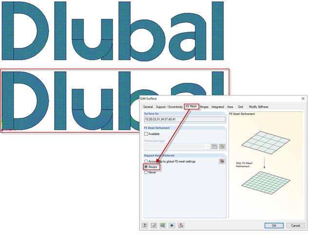
The "Mapped Mesh Preferred" option has an influence on the mesh generation of surfaces with curved and folded outlines. The program tries to align the FE mesh with the boundary lines of the surfaces.
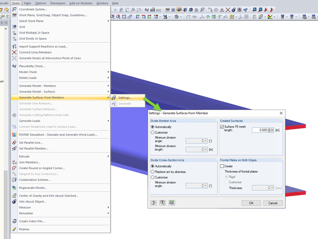
RFEM allows you to automatically generate surfaces from modeled members. This has the advantage that, for example, the surface thicknesses of a steel section are generated automatically.
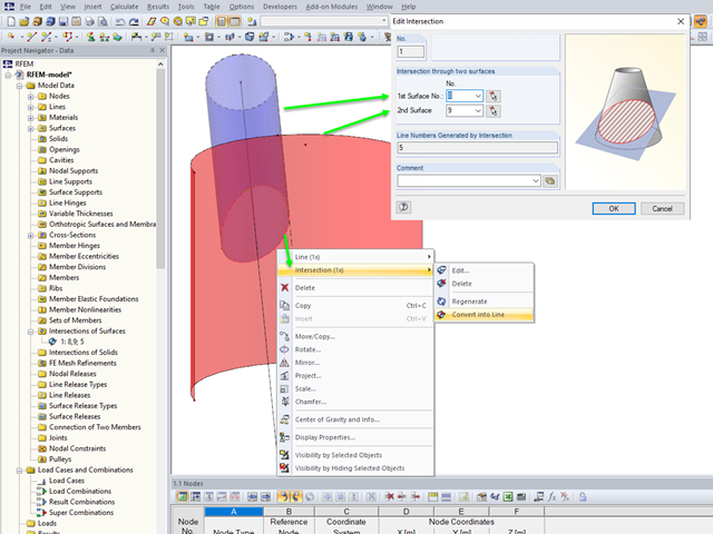
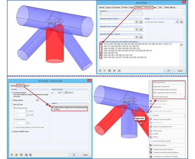
If you want to model two intersecting surfaces, RFEM offers you the possibility to create the section line automatically. In the program, this function is referred to as intersection. When generating an intersection, the modeled surface is split into components. This has the advantage that the components can be taken into account in the determination of the internal forces, or deactivated.
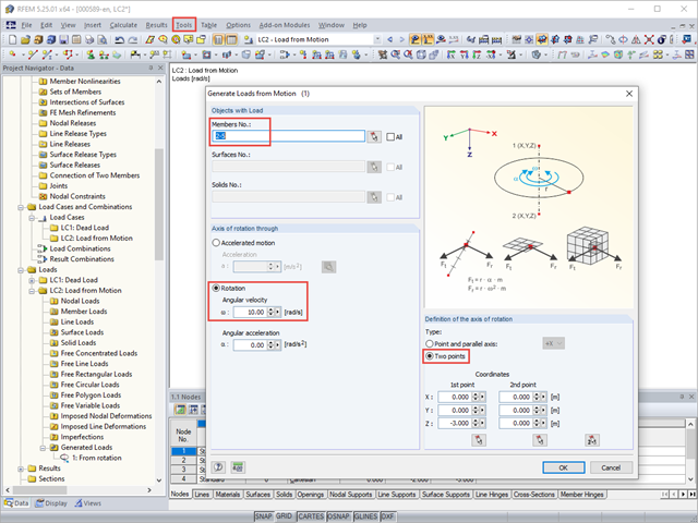
With RFEM, you can generate member, surface, or solid loads resulting from motions. Thus, for example, braking or acceleration forces can be generated automatically from linear movements or from rotational movements on a structural system.
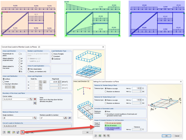
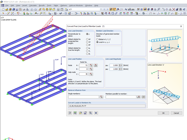
When generating member loads via plane, the program generates cells internally. These cells significantly influence the created member loads.
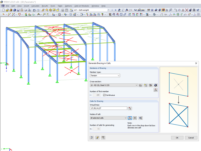
RFEM 5 and RSTAB 8 allow you to quickly and easily model bracing.
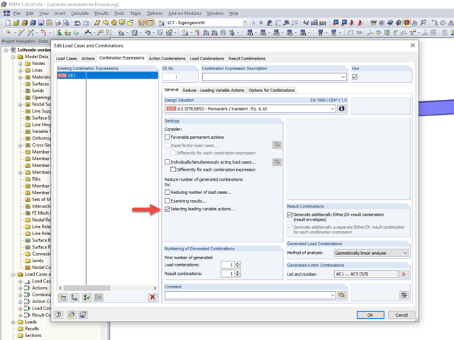
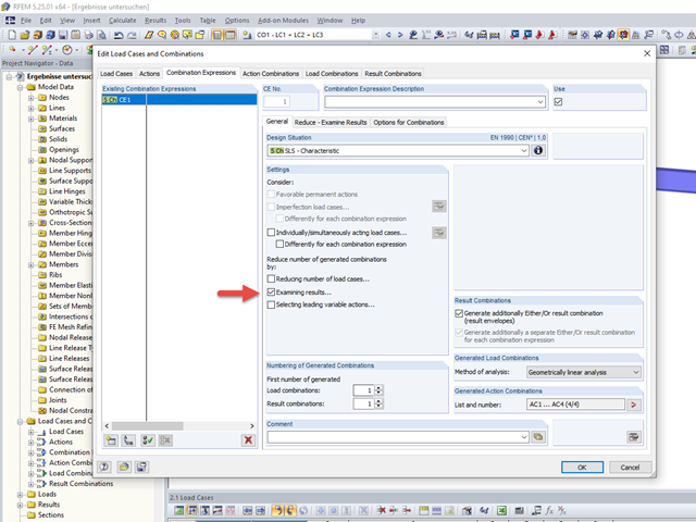
To carry out a structural analysis for a structural system according to the current standards, it is necessary not only to deal with the actions and resistances of structural components, but also with the combinations of these actions. Some of the most common actions in structural analysis are, for example, the permanently acting load case of self‑weight and the suddenly acting load cases of wind and snow.
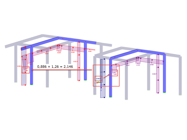
In RFEM 5 and RSTAB 8, it is possible to consider the roof overhang when generating the loads automatically.
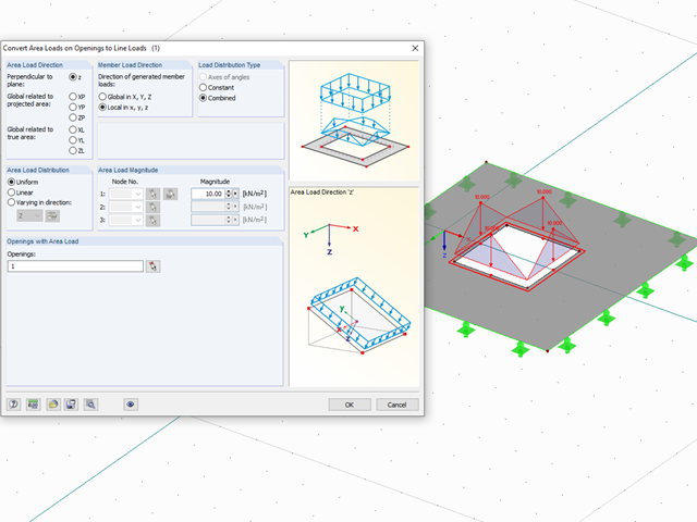
With the "Convert Area Loads on Openings to Line Loads" function, you can automatically take into account, for example, wind loads applied on windows or other loads applied on non‑bearing structures not represented in the model in openings. You can access this function via "Tools" → "Generate Loads" → "From Area Loads on Openings...."
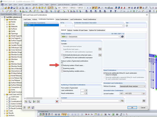
To carry out a structural analysis for a structural system according to the current standards, it is necessary not only to deal with the actions and resistances of structural components, but also with the combinations of these actions. Some of the most common actions in structural analysis are, for example, the permanently acting load case of self‑weight and the suddenly acting load cases of wind and snow.
To carry out a structural analysis for a structural system according to the current standards, it is necessary not only to deal with the actions and resistances of structural components, but also with the combinations of these actions. The best-known actions in structural analysis are, for example, the permanently acting load case of self-weight and the suddenly acting load cases of wind and snow.

Concrete on its own is characterized by its compressive strength. An important part of reinforced concrete is reinforcing steel, which contributes to both the compressive and the tension resistance of the concrete. Welded wire fabric is generally located in the tension areas of the beams or surface elements (hollow core ceiling, wall, shell) to transfer the tensile forces induced by external loading.
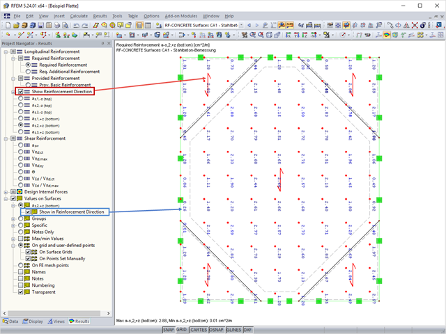
In RF‑CONCRETE Surfaces, the design of the surface reinforcement is done by means of a freely definable reinforcement mesh. In RF‑CONCRETE Surfaces, you can display the reinforcement direction by activating the reinforcement arrow that represents it.
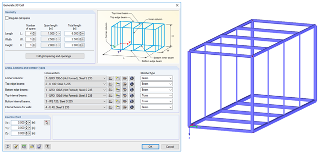
With the "Generate Model - Members" → "3D Cell" function, it is very easy to generate containers (shipping containers, office containers, mobile homes, and so on) with regular and irregular distribution of the cells.

This article describes how a flat slab is generated as a 2D model in RFEM and the loading is applied according to Eurocode 1. The load cases are combined according to Eurocode 0 and calculated linearly. In the RF-CONCRETE Surfaces add-on module, the bending design of the slab is performed while taking into account the standard requirements of Eurocode 2. The reinforcement is complemented by a rebar reinforcement for areas that are not covered by the mesh basic reinforcement.
.png?mw=640&hash=5852c5c8a1cdb9f021a168d75c0a0466fb430ef7)
Lattice towers represent typical applications in steel construction. Examples of this special type of truss structure are antenna and overhead line towers, as well as columns for wind power stations, cable cars, and supporting frame constructions. The modeling can be done individually in RFEM and RSTAB by entering various tower elements. Furthermore, you can use different copy functions and parameterized input options. However, this procedure normally requires considerable effort. It is more convenient to model such structures using prefabricated catalog elements provided by the Block Manager. These elements are automatically stored in the database during program installation. Thus, you can use tower segments, platforms, antenna brackets, cable ducts, and so on as parameterized building blocks for generating diverse tower structures.
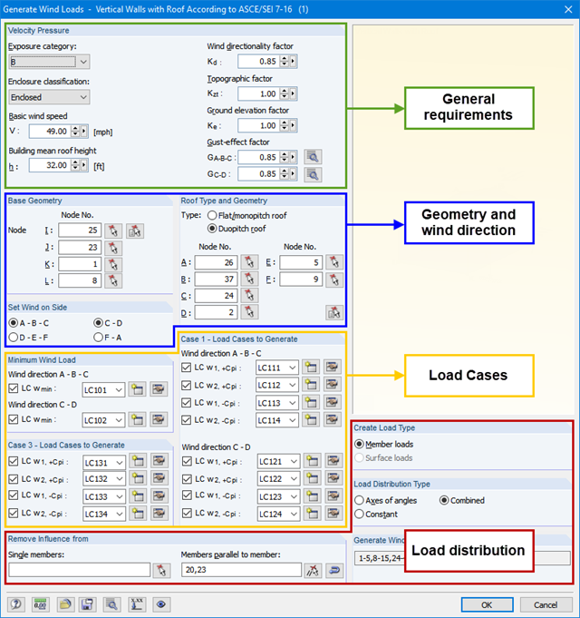
RFEM and RSTAB allow you easily to consider wind load effects on a three-dimensional building according to ASCE/SEI 7‑16. This article explains the complex theory of entering wind loads in the software. You can find the wind load under "Tools" → "Generate Loads" → "From Wind Loads".
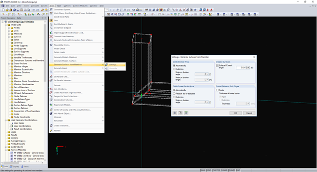
In RFEM, you can generate surfaces from members (for example, to perform an accurate FE simulation on a member). Specific parameters such as automatic FE mesh refinement or rigid surfaces can be defined prior to the generation.
If intersections created in RFEM 4 are opened in an RFEM 5 file, the file management of intersections remains in the old format for compatibility reasons. Thus, the individual partial surfaces of the intersection can be activated or deactivated using only the "Integrated/Components" tab, all partial surfaces can only have the same thickness, and it is impossible to use the separate FE mesh refinement for the individual surface components.